What are PCB components
PCB components are not only the highway between the internal components of electronic equipment, but also the core platform for electronic signal transmission and processing, whether it is 5G communication equipment for high-speed data transmission, the demanding aerospace field, or even medical Circuit systems in equipment that have extremely high requirements for accuracy are inseparable from the outstanding contribution of PCB components.
This article will help you better understand PCB components from all angles, let’s get started!
What are PCB components
On the PCB, each component has its own unique role: resistors regulate the intensity of current, capacitors store electrical energy, diodes control the direction of current, and transistors perform the tasks of switching and amplifying signals. These components are precisely laid out on specially designed copper wire paths and work together to complete complex functions.
1. Some common PCB component types
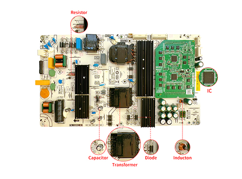
Resistor
Resistors are one of the most basic PCB components and are used to limit current, divide voltage, match loads, or build filter networks. Common resistor types include fixed resistors, adjustable resistors, thermistors, photoresistors, etc. Each type of resistor provides specific resistance value change characteristics according to different application requirements.
Capacitor
Capacitors play a vital role in storing charges, filtering, coupling signals, timing control, power supply decoupling, etc. in circuits. Common capacitor types include electrolytic capacitors, ceramic capacitors, tantalum capacitors, film capacitors, etc. Different materials and structures determine the different capacities, withstand voltages and temperature stability of capacitors..
Inductor
Inductors are used in circuits to generate magnetic fields to store energy, filter frequencies, resist electromagnetic interference, etc. They are an important part of LC oscillation circuits, filters, transformers and other components. Common types include wirewound inductors, chip inductors, ferrite beads, integrated inductors, etc. Different types of inductors have different inductances and quality factors (Q values).
Transistor
As a semiconductor device, the transistor is the basic unit for operations such as amplification, switching, voltage stabilization, and logic operations. Common types include bipolar junction transistors (BJTs), field effect transistors (FETs) such as MOSFETs, etc.
Integrated circuit (IC)
Integrated circuits (ICs) integrate a large number of transistors and other components to implement complex functions, such as microprocessors, memories, analog signal processing chips, power management chips, etc., greatly reducing circuit volume and improving integration.
Relay
Relays can use electromagnetic effects to remotely control the on and off of circuits to achieve isolation and conversion of small currents to control large currents or weak current systems to control strong current systems.
Diode
Diodes are used to conduct electricity in one direction and are used for rectification, clamping voltage, protecting circuits from reverse voltage impacts, and for functions such as switching, voltage stabilization, and lighting (LED). Common types include ordinary silicon diodes, Schottky diodes, light-emitting diodes (LEDs), varactor diodes, Zener diodes, etc.
Connector
Connectors are used to realize mechanical and electrical connections between circuits to ensure signal transmission and power supply, such as pin headers, connectors, USB interfaces, etc.
Sensor
Sensors convert physical quantities (such as temperature, light intensity, pressure, speed, etc.) into electrical signals for further processing or display.
Transformer
Transformers can change AC voltage levels, electrical isolation, and matching impedance.
Operational amplifier (Op-Amp)
Can be configured as a non-linear circuit to perform various analog signal operations such as addition, subtraction, integration, differentiation, etc.
Crystal oscillator
The crystal oscillator can provide a stable clock frequency and provide a reference clock signal for digital circuits.
Optocoupler
Optocouplers can achieve electrical isolation and transmit electrical signals from one circuit to another through optical transmission.
Switches and buttons
Manually control the opening or closing state of the circuit.
These PCB components can be roughly divided into three types: passive components, active components, and electromechanical components.
Passive components
Passive devices refer to electronic components that do not require an external power source to provide energy to function normally. They only control, limit, store or convert current or voltage and do not generate new energy. Passive components cannot amplify signals, but they can affect signal transmission through directivity (such as diodes), energy storage (such as capacitors, inductors), or impedance matching (such as transformers). Common passive components include resistors, capacitors, inductors, coil parts of relays, transformers, etc.
active components
Active components refer to electronic components that require an external power source to function properly and achieve their designed functions. Active components can amplify electrical signals, change signal properties (such as frequency, phase), or perform signal processing because they use input energy to control the amplitude, direction, or form of the output signal. Usually active devices contain one or more PN junctions, such as transistors (BJT or MOSFET), integrated circuits (ICs), operational amplifiers, microcontrollers, power management chips, etc. In a circuit, active devices can set a static operating point and have the ability to drive loads or influence the behavior of other circuit elements by controlling current or voltage.
Electromechanical components
Electromechanical components are devices that combine electronic and mechanical parts to perform a specific function. Such components often contain moving parts and can convert electrical signals into physical actions. Classic electromechanical devices include relays, solenoid valves, connectors, switches (operated manually or by electromagnetic force) and encoders/decoders, etc.
2. How to choose PCB components
Under the trend of increasingly miniaturization and high-density integration of modern electronic products, the selection of appropriate components not only directly affects the function realization and performance of the product, but also is related to the cost, volume, heat dissipation, electromagnetic compatibility (EMC), etc. of the product. aspects are closely related. Therefore, how should we choose PCB components scientifically and rationally?
Electrical performance matching
According to the functional requirements and working conditions of the circuit, select components with appropriate parameter characteristics, including but not limited to the resistance, capacitance, inductance and frequency response characteristics of passive components such as resistors, capacitors, inductors; transistors, integrated circuits Gain, switching speed, power supply voltage range, etc. of active components.
Quality control
Conduct quality inspections on selected PCB components one by one to ensure that the components comply with relevant standards set by the IPC Association, such as pad compatibility, pin size and spacing, etc., to ensure that they can match the PCB process.
Reliability and longevity
According to different operating temperature, humidity, mechanical stress and other conditions, components with corresponding tolerance are selected to ensure long-term stable operation and meet the expected service life.
Package style and size
According to the overall layout and structural design of the PCB, select the appropriate package form to adapt to space constraints and facilitate heat dissipation. At the same time, consider the needs of assembly processes and automated production, and select components that are easy to assemble and detect.
Thermal design considerations
For components with high power or severe heat generation, such as MOSFETs, IGBTs, etc., priority should be given to packaging types with excellent heat dissipation characteristics, combined with PCB copper foil routing and via design to achieve good heat dissipation effects.
Signal Integrity vs. Power Integrity
Based on the needs of high-speed digital circuits or high-frequency analog circuits, components with low noise, low distortion, and low crosstalk characteristics are selected to ensure signal quality.
High cost performance
On the basis of meeting performance requirements, through a comprehensive assessment of market supply, procurement costs, life cycle costs and other factors, a cost-benefit analysis is conducted to select components with high cost performance.
3. What are the installation techniques for PCB components?
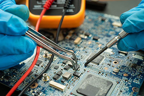
manual welding
Manual welding is the most basic installation method and is suitable for small batch production and maintenance and debugging stages. This method can be used for through-hole plug-in components (THT) such as resistors, capacitors, transistors, etc., as well as some surface mount components (SMT) such as QFP, DIP package integrated circuits, etc. However, the quality of manual welding is greatly affected by the skill level of the operator and is not suitable for large-scale automated production.
wave soldering
Wave soldering is mainly used for the installation of through-hole technology (THT) components in mass production. This technology forms a continuous wave of molten solder paste. When the PCB passes through, the component pins are automatically immersed in the solder and the soldering is completed. Suitable for installing large connectors, transformers, switches and other THT components with a large number of pins.
Reflow soldering
Reflow soldering is mainly used for the installation of surface mount technology (SMT) components, especially SMD components such as chip resistors, capacitors, IC chips, BGA, QFN, etc. First, the components are placed on the solder paste on the PCB, and then the solder paste is melted by heating, and a reliable solder joint is formed after cooling.
Selective welding
Selective soldering combines the flexibility of manual soldering with the efficiency of automated soldering, and is especially suitable for hybrid assemblies containing both THT and SMT components. It can accurately control the position and welding time of solder joints, and is suitable for components in various packaging forms, such as SOIC, PLCC, PGA and small through-hole components.
Crimp technology
Crimping technology is usually used to install components such as connectors that require high mechanical strength. Special equipment is used to press the connector terminals into the metallized holes or contact pads of the PCB to achieve electrical and mechanical connections.
Flip chip technology (Flip-Chip)
Advanced mounting technology in the field of high-density integration, suitable for high-end microprocessors and other high-performance ICs, by directly aligning the solder balls on the chip with the PCB pads and fusing the two with each other through ultrasonic waves or heat.
All in all, the choice of PCB component mounting technology not only depends on component type and packaging form, but also requires comprehensive consideration of product design requirements, production process conditions, cost control and other factors.
Regarding the technologies of SMT and THT, we have detailed explanations in another article. If you want to know more, click here – About PCB and PCBA.
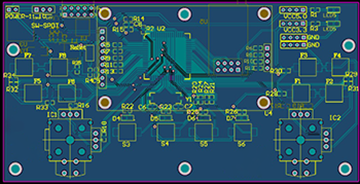
4. PCB symbols on PCB
This is a simple headline
On the PCB, there will be some alphanumeric symbols used to identify different types of electronic components. These alphabetical symbols, combined with numbers or other characters, form a specific code that provides a precise and unique identity tag for each component, ensuring consistency and accuracy from design to production. For example: “R107” represents a resistor with the serial number 107. Next, I will introduce you to some common PCB component symbols to help you understand the PCB industry more quickly.
C: Represents capacitor, R: Represents resistor, L: Represents inductor, D: Represents diode, Q: Represents transistor, U: Represents integrated circuit (IC) or chip, J: Represents connector, X: Represents crystal oscillator, T: Represents transformer, K: Representative relay.
There are also some PCB components not mentioned above:
SW: stands for switch, used to control the on and off of the circuit.
F: stands for fuse, used for overcurrent protection.
P: stands for socket, used to install and replace integrated circuit chips.
LED: stands for light emitting diode, used for indication or lighting.
VR: stands for variable resistor or potentiometer, used to adjust circuit parameters.
VCC and VSS: VCC represents positive power supply and VSS represents negative power supply.
5. Why choose XINGHONGTAI?

In modern electronic design, the selection and layout of PCB components is a key task. The correct selection and optimal design of PCB components can effectively improve the overall performance of the system, reduce the failure rate, and at the same time help meet the development trend of miniaturization and high-density integration. . We can make some optimizations based on your design plan to provide your products with better market competitiveness.
Layout optimization
We will follow the principles of short signal transmission paths and even distribution of power and ground wires to reduce noise interference and signal delays and improve signal integrity. And use advanced EDA software tools for automated layout, combined with manual adjustments, to achieve fast, efficient and accurate design results.
Hierarchical layout strategy
We adopt a multi-level layout method, first completing the layout of core components such as main control chips and power modules, and then gradually detailing the locations of other components.
Electromagnetic compatibility design optimization
We add filters and shielding covers to sensitive components, select components with low radiation and high anti-interference capabilities, and combine grounding design, shielding measures and other means to reduce the impact of electromagnetic interference on the system.
Simulation-driven iterative optimization
We will continuously optimize the preliminary layout based on the early circuit simulation results, such as SI/PI/EMI simulation feedback to guide the fine-tuning of specific component locations.
Redundant design and failsafe
We will reserve backup solutions for key components or adopt redundant designs to enhance the system’s ability to withstand faults.
Cost budget optimization
We follow the principles of Design for Manufacturability (DFM) and Design for Testability (DFT) to facilitate the production and testing process and reduce later modification and repair costs. And there will be an engineering team to analyze your solutions and discuss them with you to find lower-cost, high-efficiency PCB components and reduce your cost budget.
Summarize
Since its establishment, XHT has continued to provide high-quality PCB layout design services to global customers over the past 20 years, and has gradually formed a complete project management and technical service system. We are good at solving the wiring challenges of complex systems, and strictly follow industry standards.XHT Company uses advanced computer-aided design (CAD) tools and technology in the PCB layout process, combined with accurate simulation methods to ensure that each component is reasonably and accurately arranged in the layout. We have various types of PCB Have a deep understanding of the program. If you have any questions about PCB, please click here – Contact us, we will answer you wholeheartedly.
Hot Post